This chapter provides instructions on how to prepare the workstation for service and add, replace, and configure components. The following sections are included in this chapter:
Preparing the Workstation for Service and Operation
- Powering the Workstation On and Off
- Observing Electrostatic Discharge (ESD) Precautions
- Required Tools and Supplies
- Opening the Workstation
- Closing the Workstation and Preparing for Operation
- Component FRU and CRU List
Removal and Replacement Procedures
- Removing and Installing a Hard Drive
- Converting From SATA to SAS
- Replacing the Storage Backplane
- Replacing the DVD Drive
- Removing and Installing DIMMs
- Removing and Installing a PCIe2 x16 Card
- Adding Supplemental Power to PCIe2 Cards
- Removing and Installing PCIe Cards
- Replacing the System Battery
- Replacing the System Fan
- Replacing the Power Supply
- Replacing the I/O Board Assembly
- Replacing the System Cables
- Replacing the Heat Sink and CPU
- Replacing the Motherboard
- Updating the BIOS and Accessing the BIOS Setup Utility
Powering the Workstation On and Off
This section describes the correct procedures for powering the workstation on and off.
 To Power On the Workstation
- Turn on the power to the monitor and to all external devices.
- Turn the power switch on the rear of the workstation to the On (|) position.
- Press and release the power switch on the front panel.
- After several seconds, verify that the Platform Power LED next to the power switch is lit.
The Platform Power LED lights after the workstation begins the internal booting process.
 To Power Off the Workstation
- Save your data and close any open applications.
- Read the following power-off options and use one of the options to turn off the workstation.
In most cases, this initiates an orderly shutdown of the operating system and shuts off the workstation power.
- Power off the workstation by using the operating system shutdown command or menu option.
- If the first option does not shut off the workstation power, press and hold the power button for approximately four seconds.
This option shuts down the power to the workstation but does not initiate an orderly shutdown of the operating system. This option might result in data loss. - If the preceding options do not power off the workstation, turn the power switch on the back panel to the off (0) position.
 Caution –Potential data loss if the power is turned off using the back-panel power switch. Ensure that you have saved your data and closed any open applications before powering off the system using the back-panel power switch.
Note –After powering off the workstation, wait at least 10 seconds before powering on the workstation again.
Observing Electrostatic Discharge (ESD) Precautions
Electrostatic discharge (ESD) can damage your processor, disk drives, expansion boards, and other components. Always observe the following precautions before you install a system component:
- Do not remove a component from its protective packaging until you are ready to install it.
- Wear a wrist strap and attach it to the system chassis ground or to any metal part of the system before handling components or working in the interior compartment of the workstation.
- Turn off the power switch on the back of the chassis.
Required Tools and Supplies
These are the basic tools required for the procedures listed in this chapter:
- No. 2 Phillips screwdriver
- No. 2 Long Phillips screwdriver (longer than 6 inches)
- Flathead screwdriver
- Antistatic wrist strap (shipped with every CRU)
- Antistatic mat
Opening the Workstation
This section describes how to open and close the workstation by removing and installing the left-side access panel and the front bezel.
Do not operate the workstation for more than 10 minutes when the left-side access panel is removed. Improper cooling air flow might damage the system’s components.
 To Remove the Left-Side Access Panel
Before you remove, replace, or install any components, perform the following steps.
- Observe the ESD procedures described in the section, Observing Electrostatic Discharge (ESD) Precautions.
- Power off the workstation using the procedure described in section, To Power Off the Workstation.
- Turn the power switch on the back of the chassis to the Off position (0).
 Caution –Failure to properly turn off the system before you start installing components can cause serious component damage.
- To maintain system grounding, do not unplug the AC power cord from the back of the system unless the specific procedure instructs you to unplug it.
- Power off all peripherals connected to the workstation.
- Loosen the two captive thumbscrews located on the rear edge of the left-side access panel (see Figure 3–1).
Figure 3–1 Removing the Side Access Panel
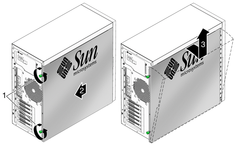
- Slide the access panel approximately 1.5 cm toward the back of the workstation.
- Tilt the top edge of the panel out, then lift the panel upward.
- Set the panel aside.
 To Remove the Front Bezel
Note –
Do not remove the front bezel unless removal is required to perform a maintenance procedure.
- Perform the steps described in the section, To Remove the Left-Side Access Panel.
- Unlatch the three left-side bezel tabs by gently pressing the side of each tab inward and slightly forward (see Figure 3–2).
The edge of the bezel nearest the tabs moves slightly away from the front of the chassis as the ridges holding each tab in place are released.
 Caution –The bezel tabs and the chassis hooks might break if you apply too much force or attempt to swing the bezel open. Be very careful when pulling the bezel away from the chassis.
Figure 3–2 Removing the Front Bezel
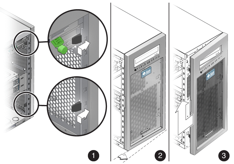
- Gently move the bezel slightly to the left and gently pull forward to disengage the three chassis hooks on the right side.
- Remove the bezel and set it aside.
Closing the Workstation and Preparing for Operation
This section describes how to prepare for service and install the left-side access panel and the front bezel.
 Close the Workstation and Prepare of Operation
Perform the following steps after installing a workstation component.
- Ensure that all the components are removed, replaced, or installed as described in the removal and replacement procedures.
- Ensure that all cables are secure and do not block the internal airflow or touch components on the motherboard.
- Remove tools and debris from the interior of the workstation.
- Install the front bezel as described in the procedure, Install the Front Bezel.
- Install the left-side access panel as described in Install the Left-Side Access Panel.
- Connect all external cables to the system, and then connect the AC power cord.
- Power on the workstation.
See To Power On the Workstation.
 Install the Front Bezel
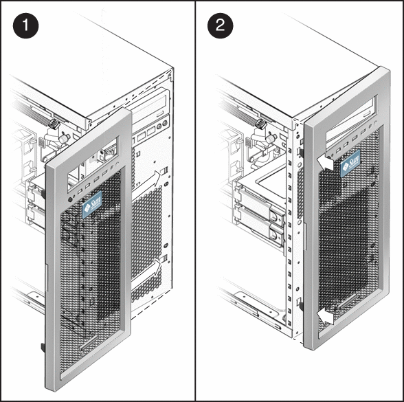
- Insert the right side bezel hooks into the right side chassis slots. See Figure 3–3.
- Insert the left-side bezel tabs into the chassis slots, and gently press the left side of the bezel toward the chassis until the tabs lock.
 Caution –Use care when installing the bezel. The bezel tabs and the chassis hooks might break if you apply too much force or attempt to swing the bezel closed.
Figure 3–3 Installing the Front Bezel
 Install the Left-Side Access Panel
Install the left-side access panel after you finish inspecting or installing components.
- If necessary, install the front bezel (see Install the Front Bezel).
- Position the access panel so that the lip on the inside bottom of the panel fits over the bottom chassis rail.
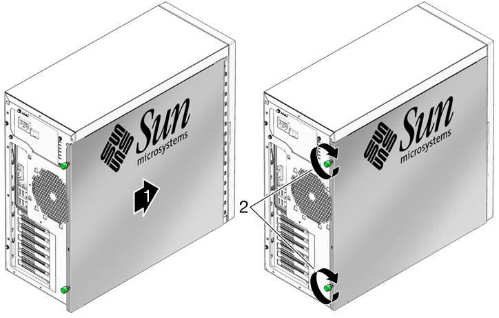
- Press gently against the side of the access panel and slide the panel toward the front of the chassis. See Figure 3–4.
The access panel lies flat against the chassis, with no gaps between the two. - Tighten the two captive thumbscrews located on the rear lip of the panel.
The access panel is installed flat against the chassis with the thumbscrews tightened.
Figure 3–4 Installing the Left-Side Access Panel
Component FRU and CRU List
Before removing, installing, or replacing system components, review the list to determine if a component is a field replaceable unit (FRU) or a customer replaceable unit (CRU). FRU components must be replaced by Sun Service personnel. Sun Service personnel are not required for the replacement of CRU components.
Table 3–1 CRU and FRU List| Description | Status |
|---|---|
| Intel® Xeon Quad-Core CPU | FRU |
| Sun Ultra 27 workstation motherboard assembly | FRU |
| Memory modules (DIMMs) | CRU |
| Hard drives | CRU |
| DVD-dual drive | CRU |
| 4–port internal SAS adapter (LSI Logic 3041E) | CRU |
| Nvidia Quadro graphics accelerator cards | CRU |
| Fan and heat sink assembly for CPU | CRU |
| Power supply (530w) | CRU |
| System fan module | CRU |
| I/O assembly | CRU |
| HD backplane assembly | CRU |
| System cable kit | CRU |
| 6–to-8 pin adapter cable (PCI auxiliary power adapter cable) | CRU |
| System battery | CRU |
Removing and Installing a Hard Drive
This section contains procedures to remove and replace a hard drive (HD). Terms used in this section are defined as follows:
- HD – A hard drive equipped with rails and a locking mechanism compatible with the HD cage in the Sun Ultra 27 workstation.
- HD cage – The metal assembly that holds the system HDs. The rails on the HDs fit into guides on the HD cage. The HD cage is not replaceable, nor is it removed during maintenance procedures.
- Storage backplane – The storage backplane is located beneath the HD cage. When correctly inserted into the HD cage, the HD makes contact with the connectors on the storage backplane. The storage backplane also has cables linking it to the power supply and to storage device connectors on the motherboard.
- Hard drive assembly – Installed HDs, the HD cage, and the storage backplane.
 To Remove a Hard Drive
Note –
The Sun Ultra 27 workstation accommodates up to four HDs. If you are not removing an existing hard drive, proceed to To Install a Hard Drive.
- Power off the workstation as described in section, To Power Off the Workstation.
- Remove the side access panel as described in section, To Remove the Left-Side Access Panel.
- Gently lay the system on its right side on a stable, nonslip surface.
- Locate the HD to be removed.
- Push the plastic latch in the direction of the engraved arrow (away from the metal locking handle) until the HD handle pops out (see Figure 3–5).
Figure 3–5 Removing a Hard Drive
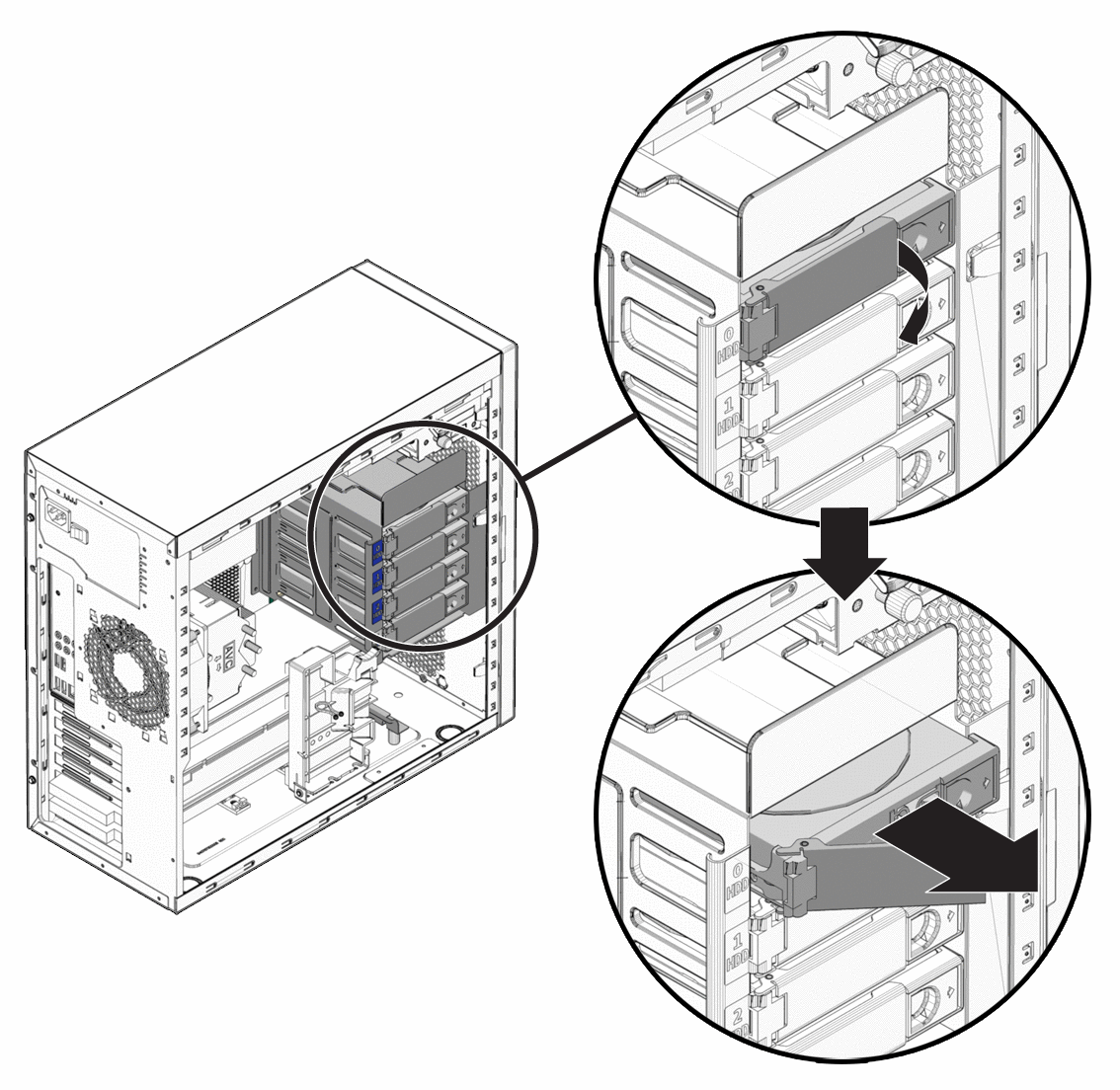
- Grasp the HD handle and pull straight out to remove the HD from the system.
- Set the HD on an antistatic surface.
- Choose your next step.
- If you removed a hard drive and want to replace it, see the procedure To Install a Hard Drive.
- If you removed a hard drive, and are not replacing it at this time, close the workstation as described in the section, Closing the Workstation and Preparing for Operation.
 To Install a Hard Drive
- Power off the workstation using procedures in section, To Power Off the Workstation.
- Remove the side access panel as described in section, To Remove the Left-Side Access Panel.
- Gently lay the system on its right side on a stable, nonslip surface.
- If you are replacing a hard drive, see To Remove a Hard Drive.
- Remove the new HD from its antistatic packaging.
 Caution –Handle the HD with care. Dropping or jarring the HD can cause damage.
- Push the plastic latch in the direction of the engraved arrow (away from the metal handle) until the HD handle pops out.
Figure 3–6 Installing a Hard Drive
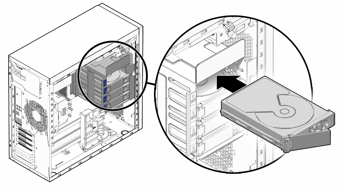
- Locate the HD assembly and HD cage guides.
You must install a boot drive in HD0, the top slot. Install a second HD in HD1, the second slot. You can install up to four HDs. The third and fourth HD slots are designated as HD2 and HD3, respectively. - Align the HD so the drive is centered with the slot numbering on the HD cage. Be sure that the labeled side of the HD faces upward and the handle hinge is on the left.
- Slide the HD into the HD cage until the metal locking handle begins to close.
Note –Press on the plastic parts on either side of the metal locking handle to ensure that the handle engages the HD cage.
- Press the metal locking handle closed until it locks the HD into the HD cage.
When correctly installed, the hard drive connector seats firmly into the storage backplane connector. - Inspect the hard drive assembly to verify the following items:
- Close the workstation using the procedure in the section, Closing the Workstation and Preparing for Operation.
Converting From SATA to SAS
 To Install SAS Card Components
To replace the SATA drives with SAS drives, use the following procedure. You will need to order a SAS installation kit that includes a SAS PCIe card, and SAS HDs.
- Power off the system using the procedure described in the section, To Power Off the Workstation.
- Remove the left-side access panel (see To Remove the Left-Side Access Panel).
- Remove the SATA HDs from the drive bay, using the procedure described in section, To Remove a Hard Drive.
- Move the HD cables from the motherboard to the SAS card as follows:
Note –To ease the installation process, connect the cables to the SAS card before inserting the card in the PCI slot.
- Release the HD cables from the tie-downs (two places).
- Disconnect the SATA1 (black connector) cable from the motherboard SATA1 connector, and install it on PHY0 of the SAS card.
- Disconnect the SATA2 (blue connector) cable from the motherboard SATA2 connector, and install it on PHY1 of the SAS card.
- Disconnect the SATA3 (green connector) cable from the motherboard SATA3 connector and install it on PHY2 of the SAS card.
- Disconnect the SATA4 (red connector) cable from the motherboard SATA4 connector and install it on PHY3 of the SAS card.
- Locate the PCIe slot 5.
You must install the SAS card in slot 5. Slot 5 is the bottom slot (see Figure 1–2 and Figure 1–3). - Using a No. 2 Phillips screwdriver, remove the chassis filler panel for the slot from the internal side of the workstation chassis back panel.
Retain the screw for the next step. - Insert the SAS card with attached cables into the PCIe slot 5, and secure the card with a screw (see Figure 3–7).
- To keep the cables out of the air flow, carefully secure them in the tie-downs.
Figure 3–7 Installing a SAS Card
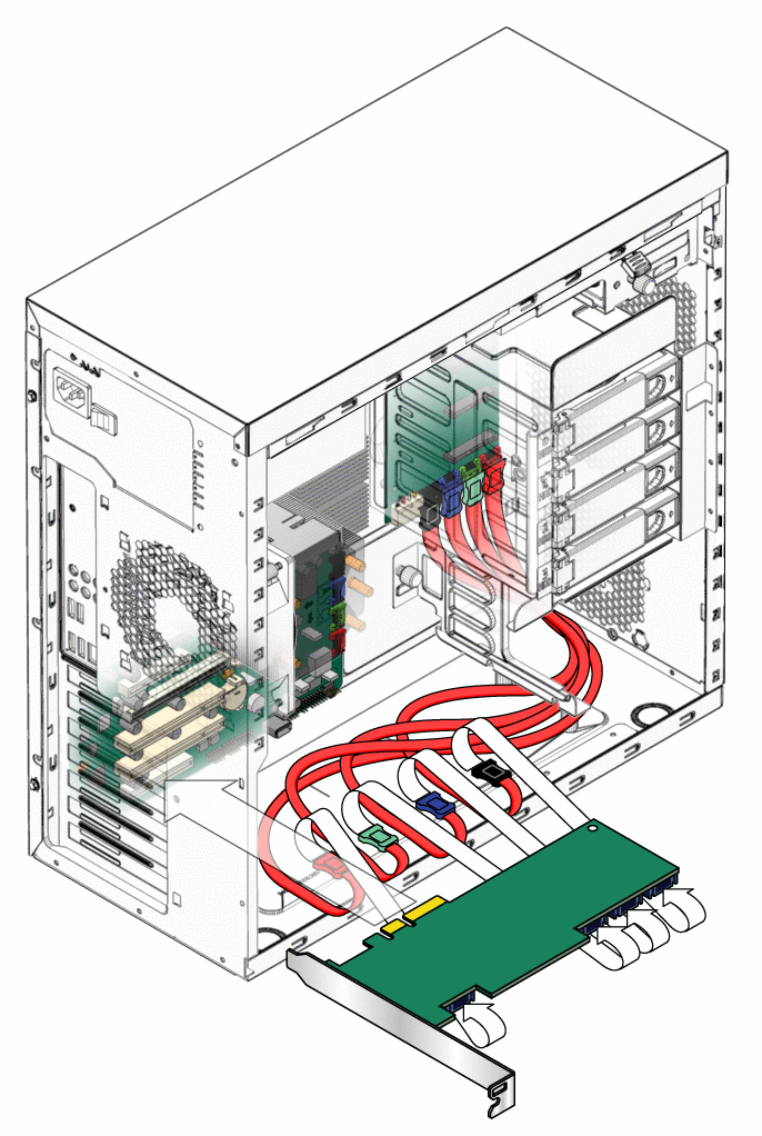
- Install the SAS drives using the procedures in the section, To Install a Hard Drive.
- If you are finished working, close the workstation using the procedures in the section, Closing the Workstation and Preparing for Operation.
- If necessary, install a new operating system for the new SAS configuration.
Refer to the Sun Ultra 27 Workstation Linux and Solaris Operating System Installation Guide or the Sun Ultra 27 Workstation Windows Operating System Installation Guidelocated with the workstation's document collection at:
http://docs.sun.com/
Replacing the Storage Backplane
This section describes how to remove and install the storage backplane. The hard drives connect to the storage backplane. You must first remove the hard drives to gain access the backplane.
 To Replace the Storage Backplane
- Power off the workstation using the procedure described in the section, To Power Off the Workstation
- Remove the left-side access panel using the procedure described in the section, To Remove the Left-Side Access Panel.
- Remove any installed hard drives from the HD assembly using the procedure in the section, To Remove a Hard Drive.
Set the hard drives aside in a safe location. After removal of the hard drives, the storage backplane is accessible (see Figure 3–8).
Figure 3–8 Location of the Storage Backplane
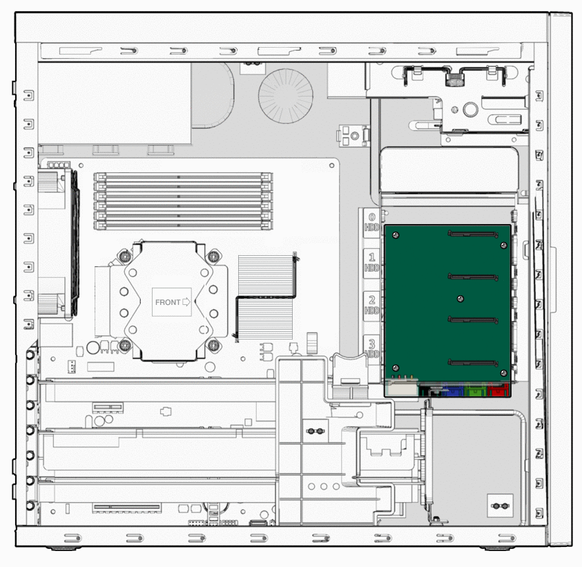
- To remove the hard drive cage support bracket, completely loosen the captive retaining screw (see Figure 3–9).
Figure 3–9 Removing the Hard Drive Cage Support Bracket
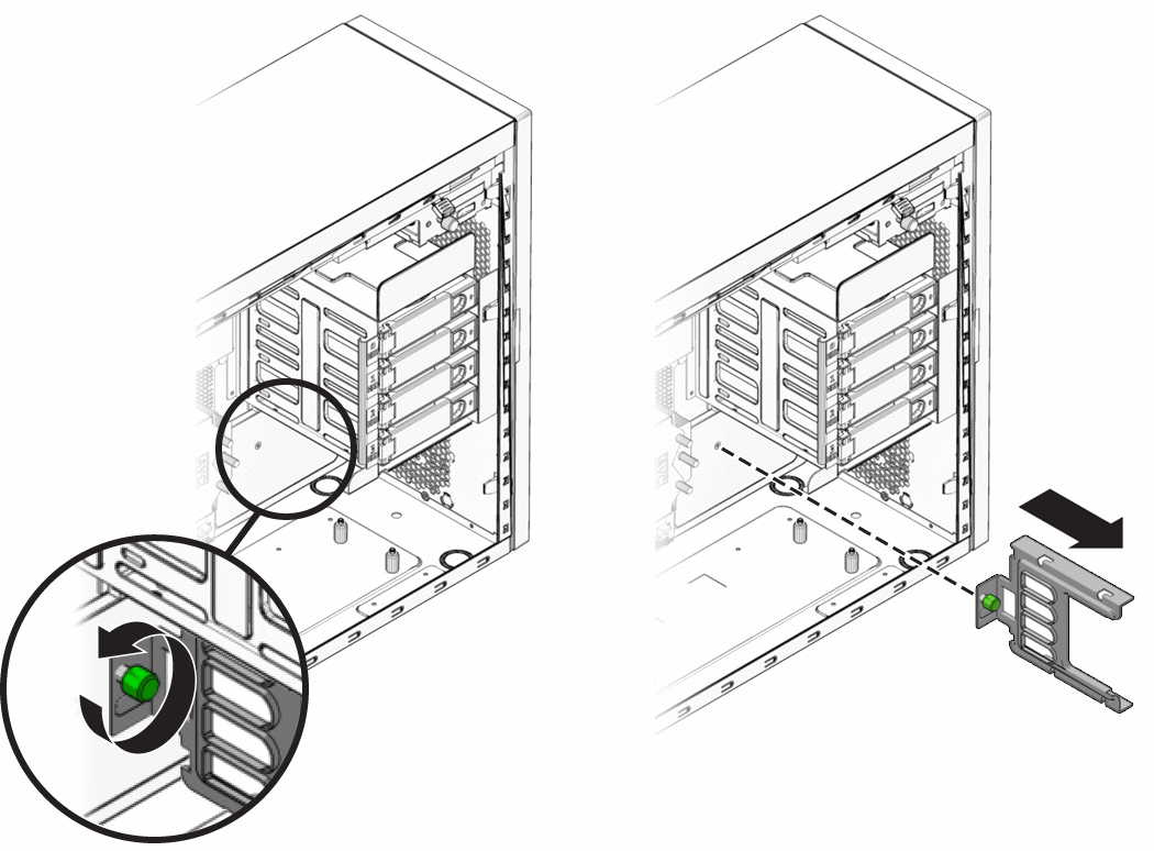
- Pull the hard drive cage support bracket away from the back wall of the interior of the workstation until it stops against the support standoffs.
- Push the top and bottom of the bracket toward the front of the workstation until it is free from the support standoffs.
- Remove the bracket from the interior of the workstation.
- Gently lay the system on its right side on a stable, nonslip surface.
- Disconnect the power connector and the black, blue, green, and red storage interface connectors.
- Using a long (more than 6 inches) No. 2 Phillips screwdriver, remove the five screws securing the storage backplane to the threaded standoffs on the chassis (see Figure 3–10).
Retain the screws.
Figure 3–10 Removing the Storage Backplane
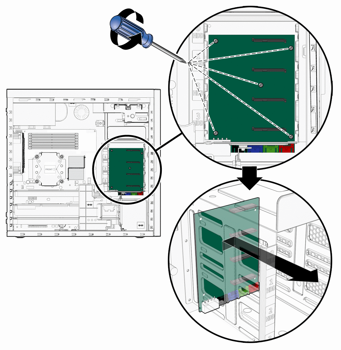
Note –Do not attempt to remove the HD cage.
- Remove the storage backplane by lifting the top edge slightly upward (to allow the connectors to clear the bottom of the hard drive cage) and pulling board up through the storage cage.
- Lower the new storage backplane into the hard drive cage connector end first and ensure that the connectors on the bottom edge of the board slip under the lower edge of the hard drive cage.
- Lay the storage backplane board onto the threaded standoffs.
Figure 3–11 Installing the Storage Backplane
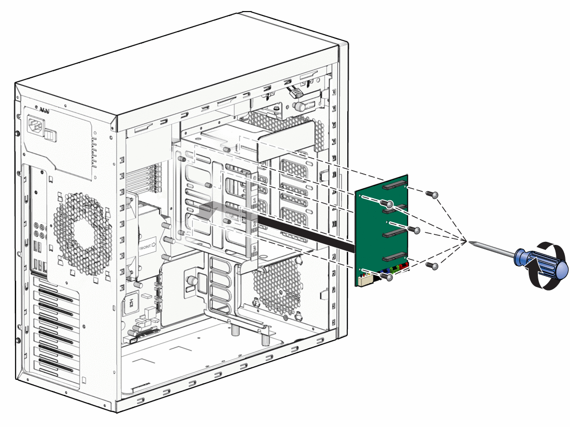
- Align the screw holes in the board with the screw holes in the threaded standoffs.
- Fasten the storage backplane to the threaded standoffs using the five mounting screws.
- Connect the power connector and the black, blue, green, and red storage interface connectors to the connectors on the bottom edge of the storage backplane board.
- Position the hard drive cage support bracket so that the edge of the bracket with the green captive screw is facing down.
Figure 3–12 Installing the Hard Drive Cage Support Bracket
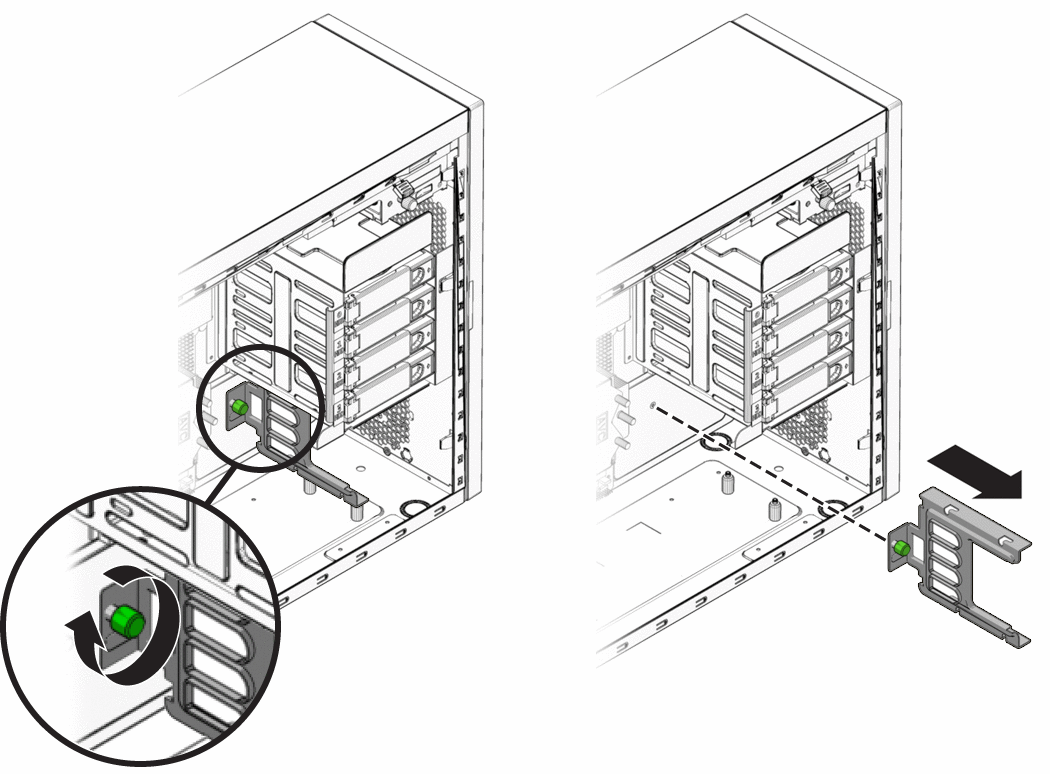
- Lower the bracket into the workstation chassis to the right of the four support bracket standoffs (two on the bottom of the hard drive cage and two on the bottom of the workstation chassis.
In this position the green captive screw does not line up with the screw hole in the back wall of the chassis. - To slip the slotted openings in the support bracket over the four support bracket standoffs, move the bracket to the left.
You might need to apply slight upward pressure against the bottom of the hard drive cage. When the bracket is in the correct position the green captive screw lines up with the screw hole in the back wall of the chassis. - To secure the bracket to the interior of the workstation, tighten the green captive screw.
- Install all hard drives into the hard drive cage using the procedure in section, To Install a Hard Drive.
- Stand the workstation upright and close the workstation using the procedure in the section, Closing the Workstation and Preparing for Operation.
Replacing the DVD Drive
 To Remove the DVD Drive
- Remove any media in the DVD drive.
- Power off the workstation using the procedure in the section, To Power Off the Workstation.
- Remove the left-side access panel using the procedure in the section, To Remove the Left-Side Access Panel.
Note –You do not need to remove the front bezel to remove the DVD drive.
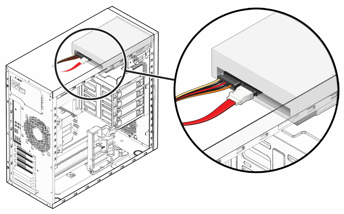
- Disconnect the cables from the back of the DVD drive (see Figure 3–13).
Figure 3–13 Location of DVD Cables
- Push the drive retaining lever tab up to release the retaining hooks (see Figure 3–14).
Figure 3–14 Removing the DVD Drive
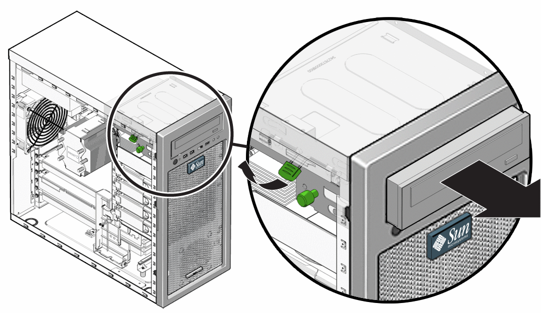
- Slide the DVD drive out from the front of the chassis.
- Install the new DVD drive using the procedure described in the section, To Install the DVD Drive.
 To Install the DVD Drive
- If necessary, do the following:
- Power off the workstation (see To Power Off the Workstation).
- Remove the left-side access panel (see To Remove the Left-Side Access Panel).
Note –You do not need to remove the front bezel to install the DVD drive.
- Remove the DVD drive (see To Remove the DVD Drive).
- Ensure that the DVD retaining lever is in the upward or disengaged position.
This prevents the retaining hooks from blocking the DVD drive when inserted. - Insert the new DVD drive into the vacant DVD housing from the front of the workstation.
- Align the locking holes in the side of the DVD drive with the slotted holes in the in the side of the DVD housing.
When the DVD is properly aligned, the front edge of the DVD drive protrudes approximately 5/8 inch (127 mm) from the front of the machine . - To engage the retaining hooks and lock the DVD, pull firmly downward on the green retaining clip handle.
Pulling downward and locking the DVD produces a click sound.
Figure 3–15 Installing the DVD Drive
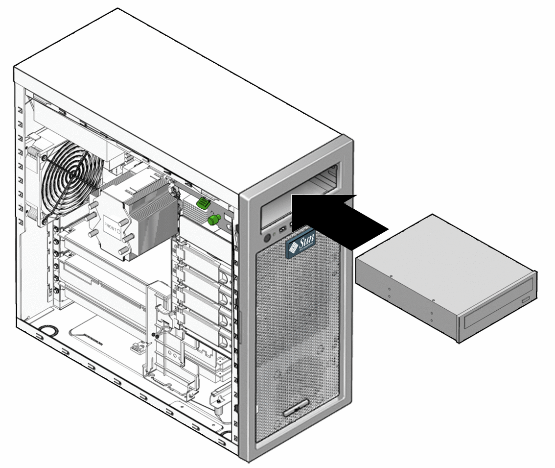
- Verify that the drive is secured with the retaining hooks by pulling on the front of the DVD.
- Connect the SATA, power, and jumper cables to the back of the DVD drive (see Figure 3–13).
Refer to the cabling diagram in the service label on the side of the chassis for information about correct cable routing. - Close the workstation and prepare for operation using the procedures described in the section, Closing the Workstation and Preparing for Operation
Removing and Installing DIMMs
This section contains instructions for removing and installing a dual inline memory module (DIMM).
DIMMs are very sensitive to ESD. Be especially careful to follow ESD precautions when changing DIMMs (see Observing Electrostatic Discharge (ESD) Precautions).
 To Remove DIMMs
- Power off the workstation using the procedures described in the section, To Power Off the Workstation.
- Remove the left-side access panel using the procedure described in the section, To Remove the Left-Side Access Panel.
- Gently lay the system on its right side on a stable, nonslip surface.
- Identify the location from which you will remove a DIMM.
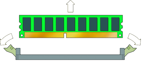
- To remove a DIMM press down on the ejector levers at both ends of the DIMM socket (see Figure 3–16).
This action ejects the DIMM from the socket.
Figure 3–16 Removing a DIMM
- Lift the DIMM and set it aside on an antistatic surface.
- Choose the next step.
- If you are installing a new DIMM, see the next section, To Install DIMMs.
- If you are finished, close the workstation and prepare it for operation using the procedures described in the section, Closing the Workstation and Preparing for Operation.
Memory Population Rules
The workstation contains six DIMM slots divided into three channels (two slots per channel). The slots are color-coded (three blue and three black) and are numbered from DIMM 0 (closest to the CPU) to DIMM 5 (farthest from the CPU).
Populate the slots according to the following rules:
- The workstation requires DDR3-1066/1333, unbuffered, ECC DIMMs.
- Supported sizes and frequencies: 1 GB and 2 GB 1066 MHz and 1333 MHz DIMMs (see the Sun Ultra 27 Workstation Product Notes for supported hardware and other workstation-related issues.)
Note –The DDR3 interface can support up to six DDR3–1066 DIMMs running at full speed.
- DIMMs must be installed in groups of three except the single DIMM configuration.
- Three 1333 MHz DIMMs will run at 1333 MHz. Six 1333 MHz DIMMs will run at 1066 MHz.
- Populate DIMMs according to the supported memory configurations listed in the following section.
Supported Memory Configurations
The following is a list of supported memory configurations for the Sun Ultra 27 workstation. Only these configurations in combination the supported DIMMs are valid:
- One DIMM in slot 1
- DIMMs in slots 1, 3, 5 only (black-colored slots only)
- All DIMM slots populated
 To Install DIMMs
This procedure describes the correct procedure for installing DIMMs.
Before You Begin
Review the following sections:
- Power off the workstation using the procedure described in the section, To Power Off the Workstation.
- Remove the left-side access panel using the procedure described in the section, To Remove the Left-Side Access Panel.
- Gently lay the system on its right side on a stable, nonslip surface.
- Identify the location into which you will install a DIMM.
Ensure that the locking tabs are rotated to the open position. - Align the DIMM with the proper slot.
Note –Be sure to align the notch in the DIMM with the notch in the connector.
- Press both ends of the DIMM downward into the slot until both locking levers click into place (see Figure 3–17).
This action locks the DIMM in the slot.
Figure 3–17 Installing a DIMM
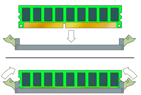
- Ensure that both locking levers are in the fully upright and locked position.
- Repeat the above steps for each DIMM that you want to replace.
- To close the system, perform the steps in the section, Closing the Workstation and Preparing for Operation.
- Boot the workstation and watch the boot messages on the monitor.
Note –The memory check shows the amount of the currently installed memory.
Watch the monitor for the prompt that instructs you to press F2 to enter the BIOS Setup utility. - When the BIOS prompt appears press F2.
The BIOS Setup utility main menu appears. - Use the Memory Configuration screen to verify that the total amount of memory installed in the workstation is seen by the system.
Removing and Installing a PCIe2 x16 Card
This section describes how to remove and install a PCIe2 card.
Note –
For information about how to remove and install a PCIe card, see Removing and Installing PCIe Cards.
 To Remove a PCIe2 x16 Card
- Power off the workstation using the procedure described in the section, To Power Off the Workstation.
- Remove the left-side access panel using the procedure described in the section, To Remove the Left-Side Access Panel.
- Gently lay the system on its right side on a stable, nonslip surface.
- Remove any cables connected to the card.
Note –Some graphics cards require supplemental power, which is supplied by connecting an auxiliary power cable directly from the power supply to the card.
- If necessary, disconnect the supplemental power connector from the card.
- Use a #2 screwdriver to remove the card retaining screw.
- Pull gently upward on the card while pressing the release latch (see Figure 3–18).
This combined action releases the card, allowing you to remove it from the workstation.
Figure 3–18 Removing a PCIe Graphics Card
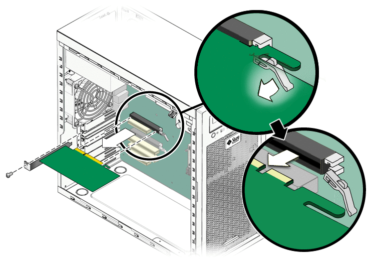
- If you are replacing the card, see To Install a PCIe2 x16 Card.
- Install the back panel slot filler using the retaining screw.
- Close the workstation and prepare for operation using the procedures in the section, Closing the Workstation and Preparing for Operation
 To Install a PCIe2 x16 Card
Note –
See PCIe and PCI Expansion Slots for PCIe slot locations and specifications.
- Power off the workstation using the procedure described in the section, To Power Off the Workstation.
- Remove the left-side access panel using the procedure described in the section, To Remove the Left-Side Access Panel.
- Gently lay the system on its right side on a stable, nonslip surface.
- Refer to the service label on the inside of the access panel or the section, PCIe and PCI Expansion Slots, to help you choose an empty card slot that is compatible with the card that you are installing.
- Use a #2 screwdriver to remove the back panel slot filler bracket.
- Position the PCIe2 x16 card in the selected slot. Ensure that the notch in the connector on the motherboard is aligned with the notch in the connector of the card and that the notch in the end of the card engages the retainer (see Figure 3–21).
Figure 3–19 Installing a PCIe Graphics Card
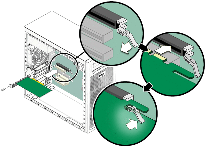
- Press down on the card until it is completely seated in the slot.
The card should sit evenly in the connector. - If you are installing a card (or cards) that requires supplemental power, see Adding Supplemental Power to PCIe2 Cards.
- Secure the card to the chassis using the retaining screw.
- Close the system and prepare for operation using the procedures described in the section, Closing the Workstation and Preparing for Operation.
Adding Supplemental Power to PCIe2 Cards
Note –
Before adding supplemental power to PCIe2 cards, review PCIe and PCIe2 slot and power specifications (see PCIe and PCI Expansion Slots).
This section contains the following procedures for adding supplemental power to PCIe2 cards in single and dual card configurations:
- To Add Supplemental Power to a Single PCIe2 Card
- To Add Supplemental Power to Two PCIe2 Cards Using the Splitter Cable
- To Add Supplemental Power to a Single PCIe2 Card Using the 8–Pin Adapter Cable
 To Add Supplemental Power to a Single PCIe2 Card
Use this procedure to add supplemental power to a single PCIe2 card (for example, Nvidia Quad FX3800).
- Locate the 6–pin auxiliary power supply cable with the connector labeled To GFX Card or Splitter and release the cable from the cable retainer.
- If the splitter cable is attached to the connector, remove and retain the splitter.
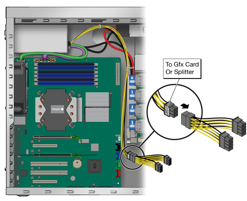
- Connect the 6–pin power supply connector to the six pin connector on the PCIe2 card.
- Secure the cable in the cable retainer.
 To Add Supplemental Power to Two PCIe2 Cards Using the Splitter Cable
Use this procedure to add supplemental power to two PCIe2 cards (for example, two Nvidia Quad FX3800 cards).
Before You Begin
You must have the auxiliary 6–pin splitter cable that was shipped with your workstation.
Note –
The 6–pin splitter cable might be installed on the 6–pin auxiliary power cable.
- Locate the 6–pin auxiliary power supply cable with the connector labeled To GFX Card or Splitter and release the cable from the cable retainer.
- If necessary, connect the 6–pin splitter cable to the 6–pin auxiliary power supply cable.
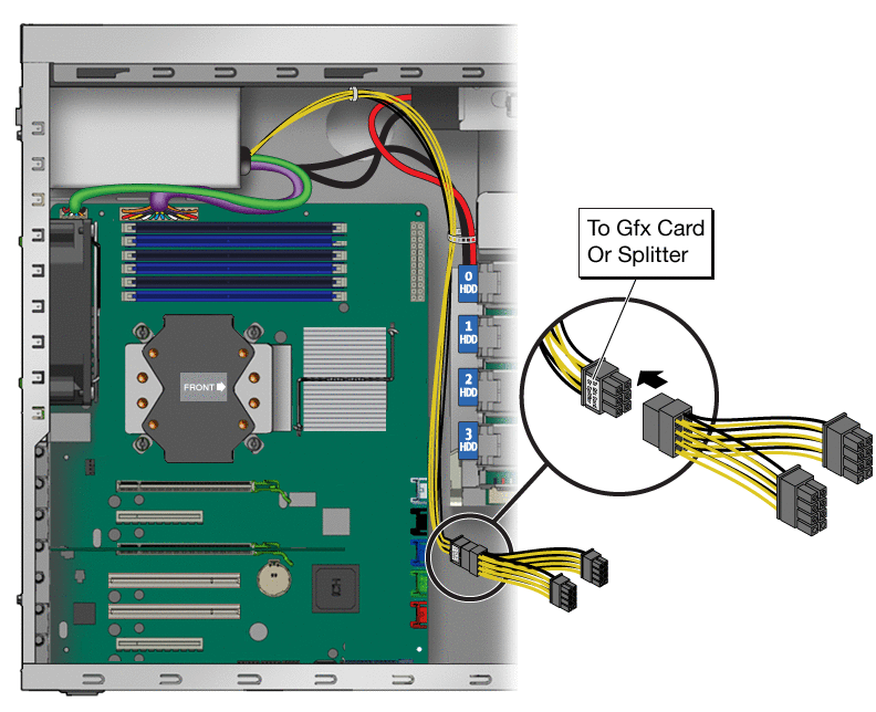
- Connect the 6–pin connectors of the splitter cable to the 6–pin connectors on the PCIe2 cards.
- Secure the cable in the cable retainer.
 To Add Supplemental Power to a Single PCIe2 Card Using the 8–Pin Adapter Cable
Use this procedure to add supplemental power to a single PCIe2 card that requires the use of the 8–pin adapter cable (for example, Nvidia Quad FX5800).
Before You Begin
You must have the auxiliary 8–pin to 6–pin adapter cable that was shipped with your workstation.
- Locate the 6–pin auxiliary power supply cable with the connector labeled To GFX Card or Splitter and release the cable from the cable retainer.
- If the splitter cable is attached to the connector, remove and retain the splitter.
- Attach the 6–pin connector on the adapter cable to the 6–pin power supply cable.
- Attach the 8–pin connector on the adapter cable to the 8–pin connector on the PCIe2 card.
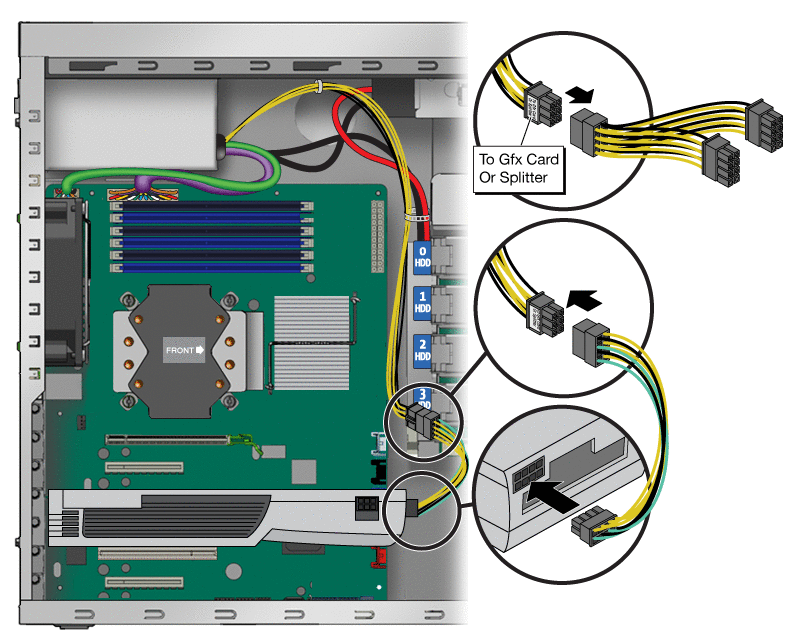
- Secure the cable in the cable retainer.
Removing and Installing PCIe Cards
This section contains procedures for removing and installing standard PCI cards.
Note –
For information about how to remove and install PCIe2 x16 cards, see Removing and Installing a PCIe2 x16 Card.
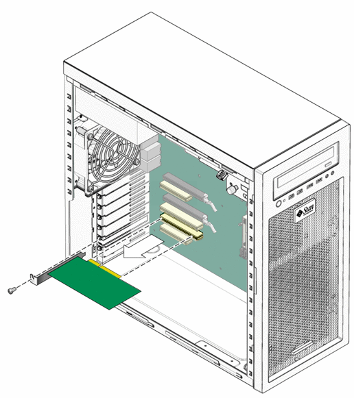
 To Remove a PCIe Card
This procedure describes how to remove a typical PCIe card (including a host bus adapter).
- Power off the workstation using the procedure described in the section, To Power Off the Workstation.
- Remove the left-side access panel using the procedure described in the section, To Remove the Left-Side Access Panel.
- Gently lay the system on its right side on a stable, nonslip surface.
- Remove any cables connected to the card.
- Use a #2 screwdriver to remove the PCIe card retainer screw.
- To remove, pull the PCIe card upward (see Figure 3–20).
Figure 3–20 Removing a PCIe Card
- Choose your next step:
- If you are not replacing the PCIe card, replace the slot filler panel, close the workstation, and prepare for service using the procedures in the section, Closing the Workstation and Preparing for Operation.
- If you are replacing the card, follow the instructions in the section, To Install a PCIe Card.
 To Install a PCIe Card
Note –
Any 64-bit PCI cards that you install will run in 32-bit mode.
Note –
Refer to the service label on the inside of the access panel or the section, PCIe and PCI Expansion Slots, to help you choose an empty card slot that is compatible with the card that you are installing.
- Power off the workstation using the procedure described in the section, To Power Off the Workstation.
- Remove the left-side access panel using the procedure described in the section, To Remove the Left-Side Access Panel.
- Gently lay the system on its right side on a stable, nonslip surface.
- Use a #2 screwdriver to remove the back panel bracket cover for the slot.
- Position the card over the selected slot and ensure that the notch in the connector on the motherboard aligns with the notch in the connector of the PCIe card.
- Press down on the card until it is completely seated in the slot.
Figure 3–21 Installing a PCI card
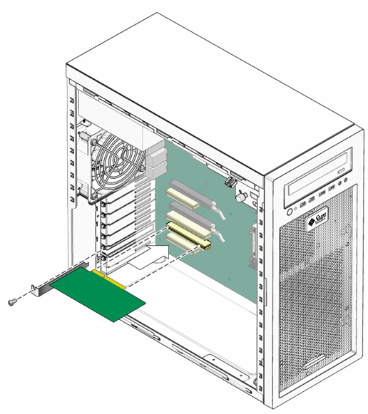
- Secure the PCIe card to the chassis back panel using the retaining screw.
- Close the workstation and prepare for operation using the procedures described in the section, Closing the Workstation and Preparing for Operation
Replacing the System Battery
The battery specifications for the Sun Ultra 27 workstation are shown in Table 3–2.
Table 3–2 Battery Specifications| Specification | Value |
|---|---|
| Voltage | 3 VDC |
| Type | CR 2032 |
 To Replace the System Battery
Removal of the system battery erases all system-specific information saved in the CMOS. Do not remove a good system battery without first recording system information.
- Power off the workstation using the procedure described in the section, To Power Off the Workstation.
- Remove the left-side access panel using the procedure described in the section, To Remove the Left-Side Access Panel.
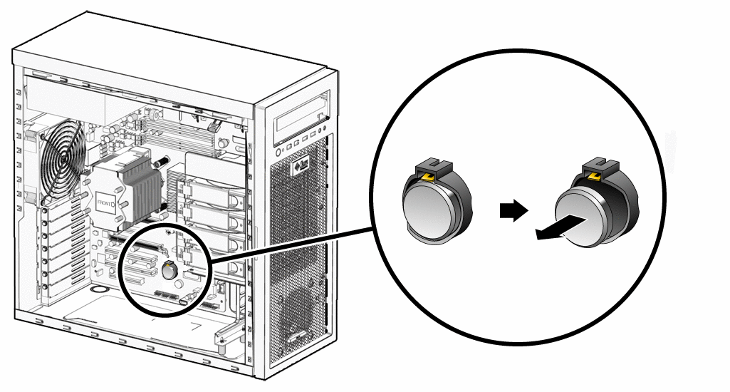
- Use the tip of a stylus or screwdriver to lift and quickly release the battery retaining latch.
This action causes the battery to eject from the battery holder.
Figure 3–22 Removing the System Battery
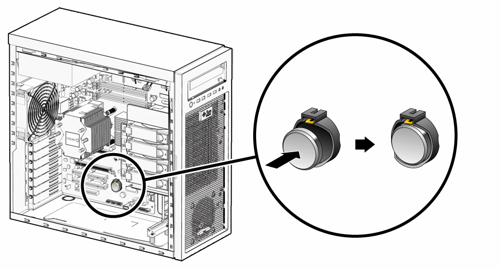
- Press the new battery with the positive sign (+) facing up into the battery holder (see Figure 3–23).
Figure 3–23 Installing the System Battery
- Close the workstation and prepare for operation using the procedures described in the section, Closing the Workstation and Preparing for Operation.
Replacing the System Fan
This workstation overheats without proper air flow through the chassis. Do not operate the workstation without a fully operational system fan.
 To Replace the System Fan
- Power off the workstation using the procedure described in the section, To Power Off the Workstation.
- Remove the left-side access panel using the procedure described in the section, To Remove the Left-Side Access Panel.
- Locate the system fan on the back inside panel of the workstation.
- Disconnect the system fan’s power connector from the SYS_FAN connector on the motherboard.
- Release the fan’s power cord from the cable management strap.
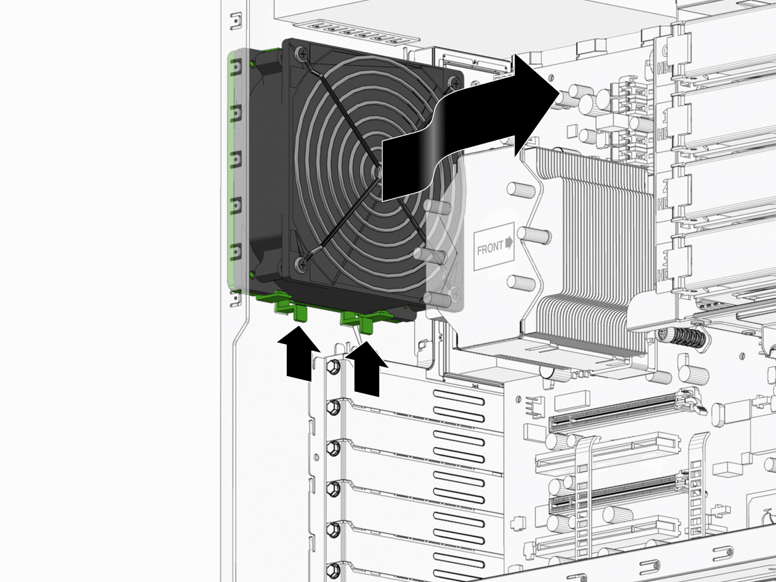
- On the interior back panel of the workstation, lift the two fan bracket chassis retaining clips.
- Slide the fan assembly down to release the four hooks on the back of the bracket from the holes in the chassis (see Figure 3–24).
Figure 3–24 Removing the System Fan
- Remove the fan from the chassis and note the orientation of the fan in the mounting bracket.
The fan is attached to a mounting bracket with four clips with the fan power cable nearest the chassis mounting clips. - To remove the fan from the fan mounting bracket, release the four retaining clips and separate the fan from the bracket.
- To install the new fan in the mounting bracket, position the fan over the bracket with the protective grill facing away from the bracket and the fan power cable positioned near the two chassis retaining clips.
- Line up the four corner pins in the bracket with the holes in the corners of the fan.
- Press the fan into the bracket.
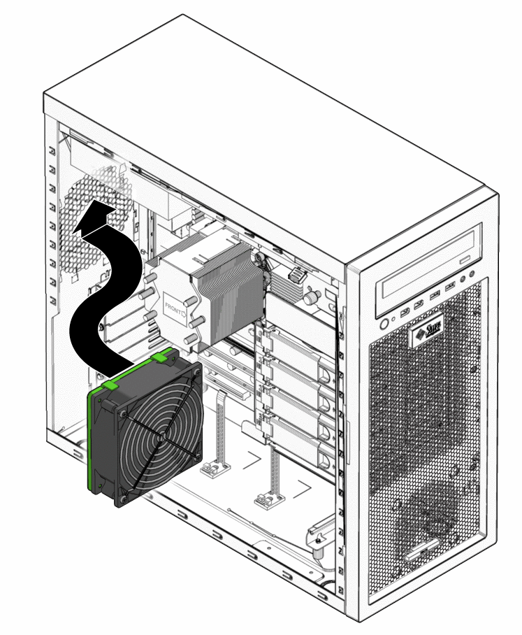
The four retaining clips secure the fan to the bracket. - Position the fan assembly against the interior chassis back panel with the four hooks on the fan bracket aligned with the four mounting holes.
- Press the fan against the back panel and slide the fan upward until the chassis retaining clips click into their locked position (see Figure 3–25).
Figure 3–25 Installing the System Fan
- Route the fan’s power cord through the cable management strap near the top right corner of the motherboard.
- Connect the fan cable to the SYS_FAN connector on the motherboard.
- Close the workstation and prepare for operation using the procedures described in the section, Closing the Workstation and Preparing for Operation.
Replacing the Power Supply
This section describes removing and installing the power supply.
 To Replace the Power Supply
- Power off the workstation using the procedure described in the section, To Power Off the Workstation.
- Remove the left-side access panel using the procedure described in the section, To Remove the Left-Side Access Panel.
- Unplug the AC power cord from the system.
- Gently lay the system on its right side on a stable, nonslip surface.
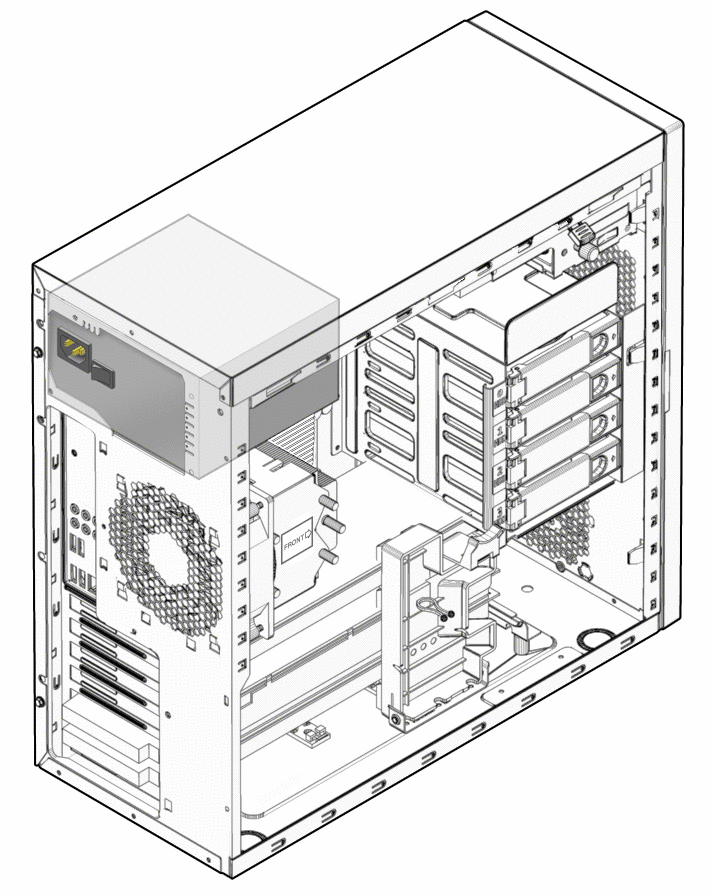
The power supply is located in the upper left corner of the interior of the chassis (see Figure 3–26).
Figure 3–26 Location of the Power Supply
- Disconnect the power connectors attached to the motherboard, DVD drive, and storage backplane.
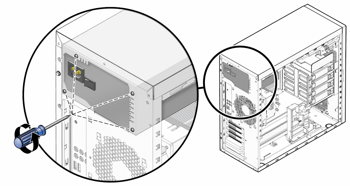
For locations of the power suply connections, see Figure 1–4. - While supporting the power supply from the interior of the workstation chassis, unscrew the four mounting screws on the back panel (see Figure 3–27).
Retain the four screws. - Remove the power supply from the interior of the system chassis.
Figure 3–27 Removing the Power Supply From the Chassis
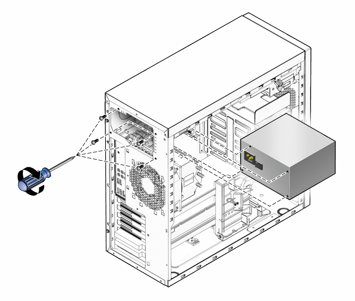
- Position the new power supply against the internal back panel and align the holes in the power supply with the holes in back panel.
- Secure the power supply with the four screws.
Figure 3–28 Installing the Power Supply
- Connect the power supply cables to the connectors on the motherboard, the DVD drive, the storage backplane, and the graphics card (optional).
- Close the workstation and prepare for operation using the procedures described in the section, Closing the Workstation and Preparing for Operation
Replacing the I/O Board Assembly
The I/O board assembly sits beneath the DVD drive and contains the power switch, Power LED, and external connectors for the front panel.
 To Replace the I/O Board Assembly
- Power off the workstation using the procedure described in the section, To Power Off the Workstation.
- Remove the left-side access panel using the procedure described in the section, To Remove the Left-Side Access Panel.
- Remove the front bezel using the procedure described in the section, To Remove the Front Bezel.
- Disconnect the audio cable (J1), the USB cable (J5), the IEEE 1394 cable (J8), and the I/O cable (J12) from the back side of the I/O board.
- Loosen the captive screw that secures the I/O board to the metal frame (see Figure 3–29).
Figure 3–29 Removing the I/O Board Assembly
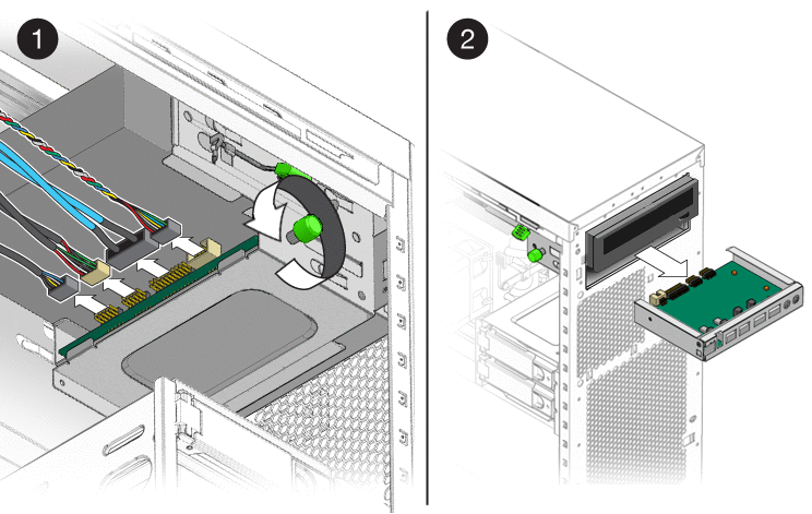
- Push the I/O board assembly out the front of the chassis.
- Slide the new I/O board assembly through the vacant I/O slot in the front of the workstation.
- Align the screw hole in the I/O board assembly with the captive green retaining screw and tighten the captive screw to secure the I/O board (see Figure 3–30).
Figure 3–30 Installing the I/O Board Assembly
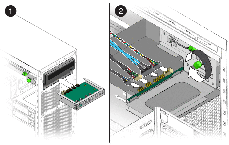
- Connect the audio cable (J1), the USB cable (J5), the IEEE 1394 cable (J8), and the I/O cable (J12) from the back side of the I/o board.
- Close the workstation and prepare for operation using the procedures described in the section, Closing the Workstation and Preparing for Operation
Replacing the System Cables
 To Replace the System Cables
The following system cables have a connector at each end and can be removed or installed by the customer. All other cables are permanently attached to a system component at one end and must be removed or replaced along with the component. See or the service label (located on the left-side access panel) for connector locations.
Do not force connectors. Connectors are designed to fit one way only. Forcing a connection can cause shorting and component failure.
Each cable connector on the motherboard is labeled to help you identify the cable to which it should be connected.
- Power off the workstation using the procedure described in the section, To Power Off the Workstation.
- Remove the left-side access panel using the procedure described in the section, To Remove the Left-Side Access Panel.
- Gently lay the system on its right side on a stable, nonslip surface.
- Remove and replace any cables that need to be replaced.
As you install each cable, connect one end to the appropriate connector, then route the cable through the cable management straps before connecting the second connector. - Ensure that all cable routing is correct and that all of the cable connectors are properly seated.
- Close the workstation and prepare for operation using the procedures described in the section, Closing the Workstation and Preparing for Operation
Replacing the Heat Sink and CPU
Note –
The CPU is a field replaceable unit (FRU) and should be replaced only by trained field service technicians.
Required tools:
- A long blade Phillips screwdriver (minimum six inches)
- Antistatic wrist strap and mat
Note –Before removing the CPU from the motherboard, create a backup file to preserve all important data.
 To Remove the Heat Sink and CPU
- Power off the workstation using the procedure described in the section, To Power Off the Workstation.
- Remove the left-side access panel using the procedure described in the section, To Remove the Left-Side Access Panel.
- Gently lay the system on its right side on a stable, nonslip surface.
- Disconnect the heat sink’s CPU fan cable from its connector on the motherboard.
The CPU fan connector is labeled CPU_FAN. - Remove the heat sink assembly by alternately loosening (2-3 turns) the four captive screws that secure the heat sink assembly to the motherboard. Continue loosening each screw until all the screws are no longer securing the heat sink (see Figure 3–31).
The heat sink assembly is also mounted to the top surface of the CPU by a layer of thermal compound.
Figure 3–31 Removing the Heat Sink-Fan Assembly
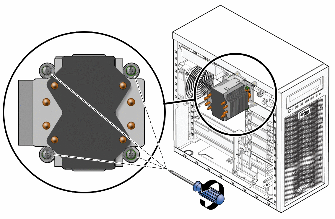
- Grasp the heat sink by its plastic mounting bracket, and, while gently pulling upward, slowly wiggle the assembly back and forth to break the adhesive seal of the thermal compound.
- Remove the heat sink-fan assembly from the chassis.
- Place the heat sink on its side and on a flat surface to prevent the thermal compound from contaminating other components and the work space.
- Depress the CPU socket retainer lever and slightly pull the lever outward (away from the CPU) to free the lever from its retaining clip (see Figure 3–32).
- When you have released the lever from the retaining clip, lift the lever to its fully open (upright) position.
This action releases the pressure on the hinged CPU socket retainer. The top of the CPU has some residual thermal compound. - Lift the unhinged side of the CPU socket retainer to its fully open (upright) position.
This action exposes the CPU. The CPU is mounted to a PCB that is keyed (notched) on two opposite sides.
Figure 3–32 Removing the CPU From the Workstation

- Grasp the notched edges of the CPU PCB and lift it out of the socket.
Set the CPU on an antistatic mat or surface. - Remove the new CPU from the antistatic packaging.
- Ensure that the CPU socket retainer lever and hinged socket retainer are in the fully open (upright) position (see Figure 3–33).
- Remove the new CPU from its antistatic packaging.
The CPU is mounted on a PCB that is notched on two opposite sides. - Hold the CPU by its notched sides.
- Position the CPU over the CPU socket so that the notches on the PCB align with the keys on the socket.
 Caution –Irreparable damage to the motherboard can occur if downward force is applied to the socket. Do not force the CPU into the socket.
- Carefully set the CPU onto the socket.
When correctly positioned the CPU lies flat in the socket, and the notches on the CPU are aligned with the keys on the socket, restricting movement of the CPU within the socket.
Figure 3–33 Installing the CPU

- When the CPU is positioned in the socket, lower the hinged socket retainer.
- Lower the socket retainer lever, pressing it downward, and secure it under the lever retaining clip.
- Do this step only if you are installing a new CPU. If you are installing a used CPU, go to Step 22.
- Gently wipe the top of surface of the CPU, using the supplied alcohol wipe, and allow to dry.
The heat sink assembly has thermal compound pre- applied. Do not apply additional thermal compound to the top of the CPU. The thermal compound on the heat sink is protected by plastic cover. - Remove the plastic cover that protects the thermal compound on the bottom of the heat sink assembly.
- Go to Step 23.
- Gently wipe the top of surface of the CPU, using the supplied alcohol wipe, and allow to dry.
- Do this step if you are installing an already-used CPU onto a new motherboard. Otherwise, go to Step 23.
- Use an alcohol-soaked wipe to remove the thermal compound from the top of the CPU and the bottom of the heat sink.
- Use the supplied syringe to apply approximately 0.5 ml of thermal compound in a star pattern to the center of the top of the CPU.
Use the entire contents of the syringe. - Using the clean edge of a plastic bag, spread the thermal compound until it covers the top of the CPU in a thin, uniform layer.
 Caution –Do not use an unprotected finger to spread the thermal grease. The oil on your finger will degrade the performance of the thermal grease.
- Inspect the heat sink-fan assembly for dust and lint. Clean if necessary.
- Carefully position the heat sink-fan assembly over the CPU so that the arrow on the top points toward the front of the workstation.
- Align the four captive screws on the heat sink assembly with the holes in the motherboard.
- Lower the heat sink-fan assembly onto the top of the CPU, avoiding any side-to-side movement. See Figure 3–34.
Figure 3–34 Installing the Heat Sink-Fan Assembly
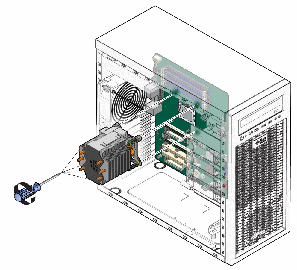
 Caution –If you move the heat sink assembly too much during installation, the layer of thermal grease might not be distributed evenly, leading to component damage.
- Press down slightly on the top of the heat sink-fan assembly while alternately tightening (3–5 turns) each of the four screws.
Continue doing this until the heat sink-fan assembly is secured to the motherboard and you can no longer tighten the screws.
 Caution –Irreparable damage can occur to the motherboard if you attempt to overtighten the heat sink-fan assembly screws.
- Connect the heat sink cable to the connector on the motherboard.
- Close the workstation and prepare for operation using the procedures described in the section, Closing the Workstation and Preparing for Operation.
Replacing the Motherboard
The following sections describe how to remove and install the Sun Ultra 27 workstation system motherboard.
Note –
The motherboard is not a CRU and should be replaced only by trained field service technicians.
 To Remove the Motherboard
- Power off the workstation using the procedure described in the section, To Power Off the Workstation.
- Remove the left-side access panel using the procedure described in the section, To Remove the Left-Side Access Panel.
- Gently lay the system on its right side on a stable, nonslip surface.
- Remove the fan assembly using the procedure described in the section, Replacing the System Fan.
- Remove any PCIe cards installed on the motherboard (see Removing and Installing PCIe Cards).
- Remove the DIMMs from the motherboard using the procedure in the section, To Remove DIMMs.
- Remove heat sink and CPU from the motherboard using the procedure in the section, To Remove the Heat Sink and CPU.
- Disconnect and label all cables attached to the motherboard.
- Remove the eight Phillips screws that fasten the motherboard to the chassis (see Figure 3–35).
Figure 3–35 Removing the Eight Motherboard Screws
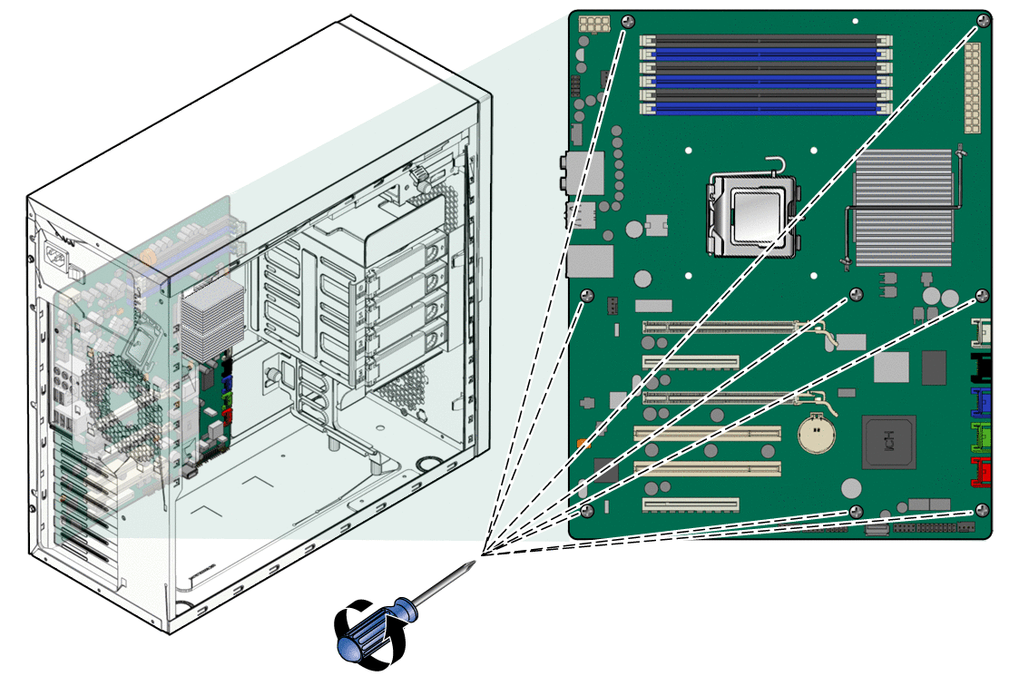
- Lift the motherboard away from the chassis.
 Installing the Motherboard
Observe proper antistatic precautions when handling a new motherboard.
- Remove the new motherboard from its protective antistatic packaging.
- Position the motherboard so that the back panel I/O connectors (audio and USB ports) are on the upper left.
- Place the motherboard in the chassis on top of the standoffs.
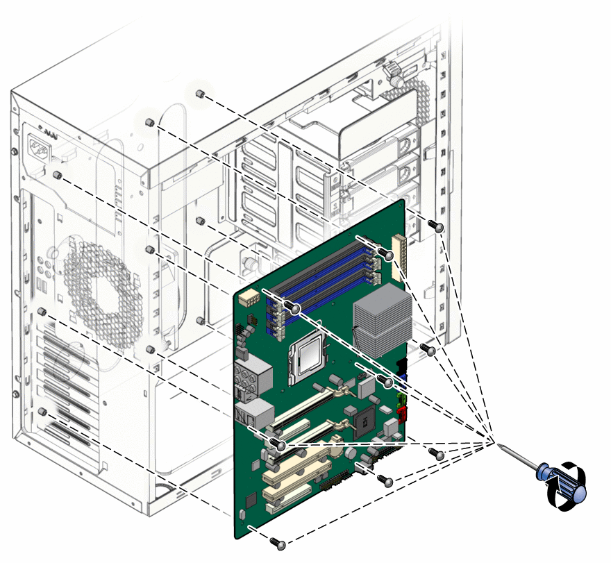
- Slide the motherboard toward the chassis back panel until the I/O ports on the upper left side of the motherboard engage the opening in the chassis back panel and the screw holes in the motherboard align with the screw holes in the standoffs.
The screw holes must align. - Secure the motherboard to the chassis using the nine Phillips-head screws (see Figure 3–36).
Figure 3–36 Installing the Motherboard
- Connect the system cables to the motherboard.
- Install the system fan using the procedure described in the section, Replacing the System Fan.
- Install the CPU and heat sink using the procedure described in the section, Replacing the Heat Sink and CPU.
- Install the DIMMs using the procedure described in the section, To Install DIMMs.
- Install any PCIe cards using the procedures described in the sections:
- Verify that all system components are securely installed or connected.
- Close the workstation and prepare for operation using the procedures described in the section, Closing the Workstation and Preparing for Operation.
Updating the BIOS and Accessing the BIOS Setup Utility
Refer to the Sun Ultra 27 Workstation Product Notes for information on BIOS updates.
 To Update the BIOS
- Power off the workstation using the procedure described in the section, To Power Off the Workstation.
- Access the BIOS using the procedure in the section, To Access the BIOS Setup Utility.
- Record any BIOS settings that might have been changed from the default value for your environment.
Note –Flashing the BIOS restores all settings to the default values.
- Press the Esc key to exit the BIOS Setup utility without saving.
- Download the latest Sun Ultra 27 workstation Tools and Drivers DVD ISO image from the Sun web site:
http://www.sun.com/downloads
 Caution –Ensure that you download the ISO image for the Sun Ultra 27 workstation.
- Burn the image to a DVD.
- Insert the DVD into the DVD drive and reboot the workstation.
The workstation boots from the DVD and a menu appears. - Choose the option to flash the BIOS (option 2).
- Respond to the prompts, and then wait until the BIOS update is complete.
- Access the BIOS Setup utility using the procedure described in the section, Updating the BIOS and Accessing the BIOS Setup Utility.
- When the workstation reboots, remove the Tools and Drivers DVD from the DVD drive.
 To Access the BIOS Setup Utility
The BIOS Setup utility enables you to customize the workstation for your local environment. Access the BIOS Setup utility after the following situations:
Be careful when making changes to the system BIOS, as some changes can cause your system to malfunction.
- Performing a BIOS update
- Adding or removing a system component
- Replacing the system battery
- Reboot the system.
Watch the monitor for the prompt to press the F2 key to access the BIOS. - When the BIOS access prompt appears, press the F2 key.
The BIOS Setup screen appears. - Use the arrow keys to access the various screens.
- Press the F10 key to save changes and exit or the Esc key to exit without saving.
The system reboots.
https://docs.oracle.com/cd/E19127-01/ultra27.ws/820-6776/z40001fc1036752/index.html


0 comments:
Post a Comment